Mechanical Design & Assembly
1. Choice of Robot Structure
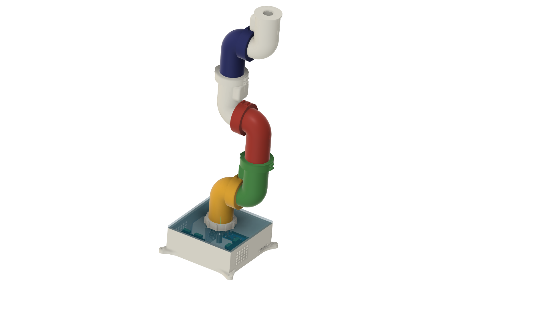
The physical architecture of this 7-Degree-of-Freedom (7-DoF) arm was driven by a core philosophy: achieve commercial-grade capabilities and aesthetics without the "spaghetti" look of external wiring. External wires are a common pitfall in DIY builds—they not only look messy but severely limit the operational workspace by creating snag points and restricting rotation. To solve this, the structure relies entirely on an internal wiring path. Mechanically, the goal is highly ambitious for a printed build: providing enough structural rigidity and torque to lift a payload of 2 to 3 kg at a maximum reach of 1 meter.
2. 3D Modelling & Innovations
To achieve the necessary strength while maintaining a hollow center, several custom mechanical solutions were engineered during the CAD phase.
Custom Planetary Gearboxes
To achieve the necessary payload capacity without compromising the arm's sleek, visually compact profile, every joint utilizes a custom 3D-printed planetary gearbox. Standard stepper motors, from the heavy-duty NEMA 23s at the base to the ultra-compact 20mm NEMA 17s in the wrist, lack the native high torque required for direct drive. By integrating a planetary gear system, a massive 70:1 reduction ratio is achieved. This design choice was specifically selected because planetary gearboxes share the same central axis as the motor shaft, significantly boosting torque output while maintaining a tight, cylindrical footprint at each joint.
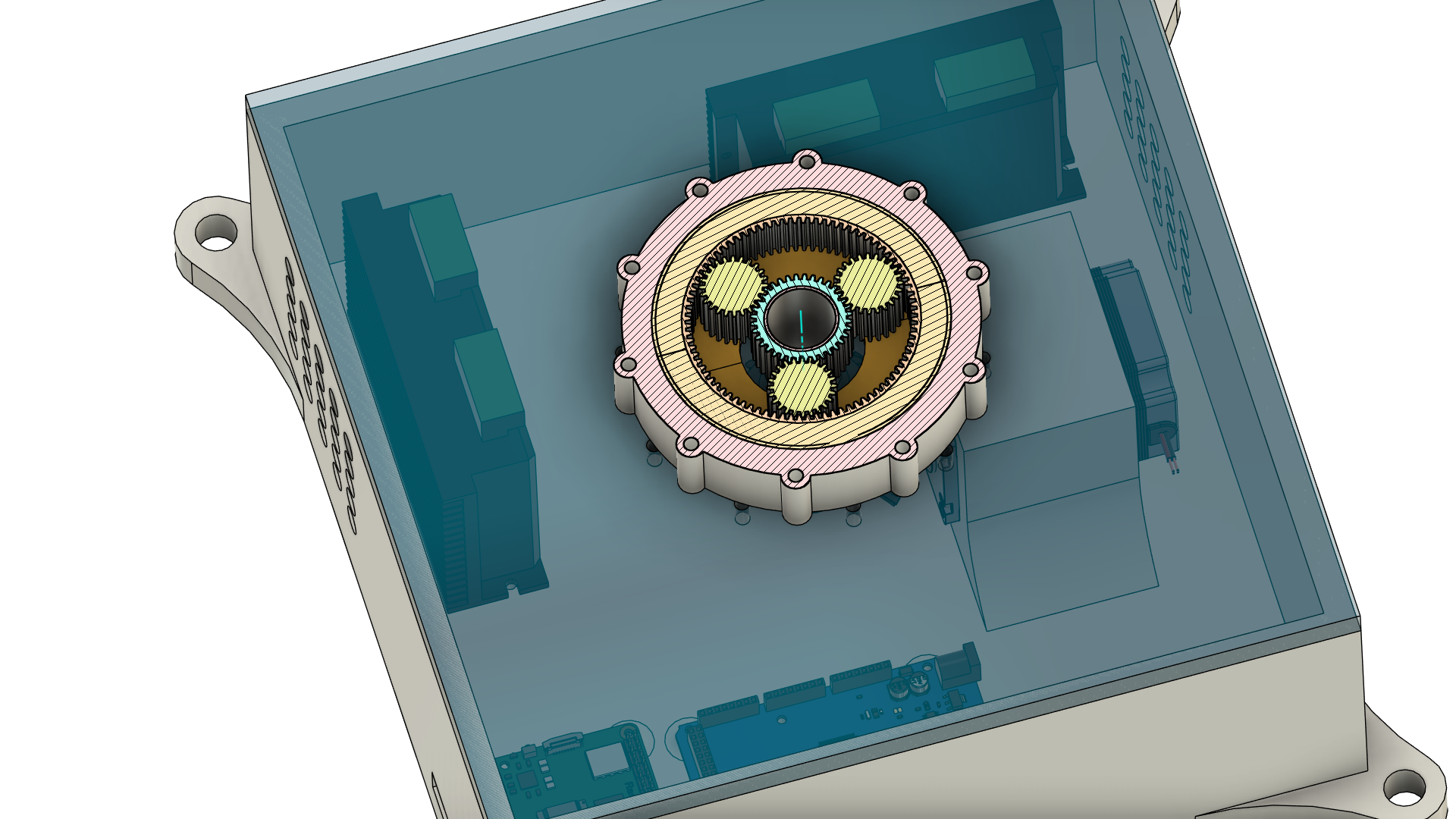
| Gear Type | Tooth Count |
|---|---|
| Sun Gear | 36 Teeth |
| Planet Gears | 24 Teeth |
| Outer Ring | 84 Teeth |
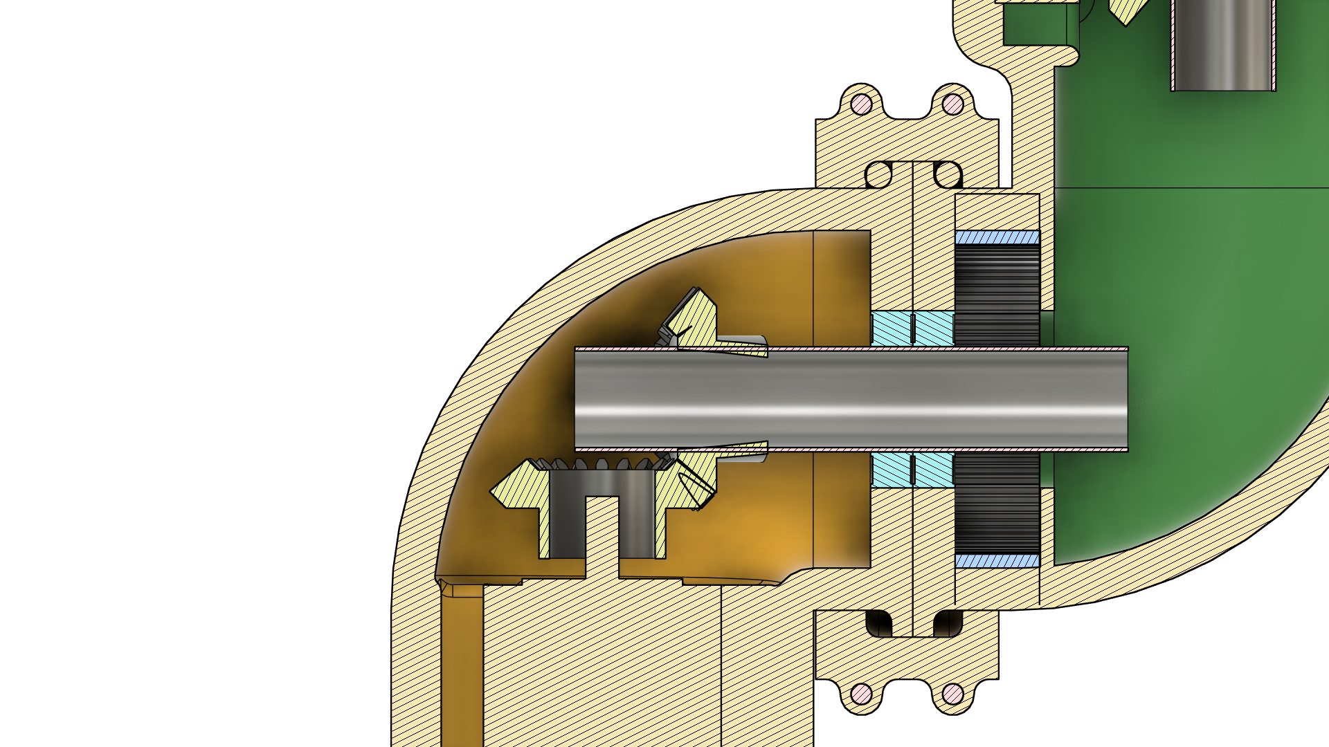
Internal Cable Management (The Hollow Shaft)
Instead of routing cables over the outer shells of the joints, the design utilizes hollow aluminum shafts coupled with slip rings. This allows the arm to achieve continuous 360° rotation (and beyond) on its axes without any risk of wires tangling, twisting, or snapping inside the housing.
Custom Bearing System
Standard robotic joints often rely on a single central pivot bolt, which obstructs internal wire routing. To maintain a hollow center while ensuring structural rigidity, a custom integrated bearing system is utilized. These bearings are seated within 3D-printed channels that act as races for loose bearing balls.
This custom bearing system is the mechanical keystone of the arm, serving three distinct primary purposes:
- Load Distribution: The system acts as a secondary bearing to the central core bearing, effectively sharing the mechanical load and reducing stress on the primary axis.
- Joint Coupling: It serves as the physical interface used to couple two separate joints together (e.g., connecting Joint 3 to Joint 4).
- Link Assembly: Because each robotic link is 3D printed in two halves to allow internal access, the custom bearing acts as the structural coupler that joins these two parts into a single, rigid link.
To support the required payload and these integrated roles without flexing, the joint walls are heavily reinforced to approximately 1 cm thick. The assembly is secured using four M5 screws and nuts, which lock the bearing system and the split-shell housing into a unified structure.
3. Motor Selection: A Load Distribution Analysis
This section explains the process used to determine the correct stepper motors and gearboxes for the 7-DOF-arm-robot project. The selection is derived from a rigorous engineering analysis of required torque under worst-case loading scenarios, visualized in the load distribution diagram provided below.
Load Diagram Overview
The following diagram is a foundational verification tool for the mechanical design. It presents two primary perspectives for calculating required torque: a Side View and a Top View. By placing the arm in its least efficient (worst-case) extended pose and calculating the resultant torque at each joint pivot point, it is possible to verify that the proposed motor combinations have sufficient power margin.
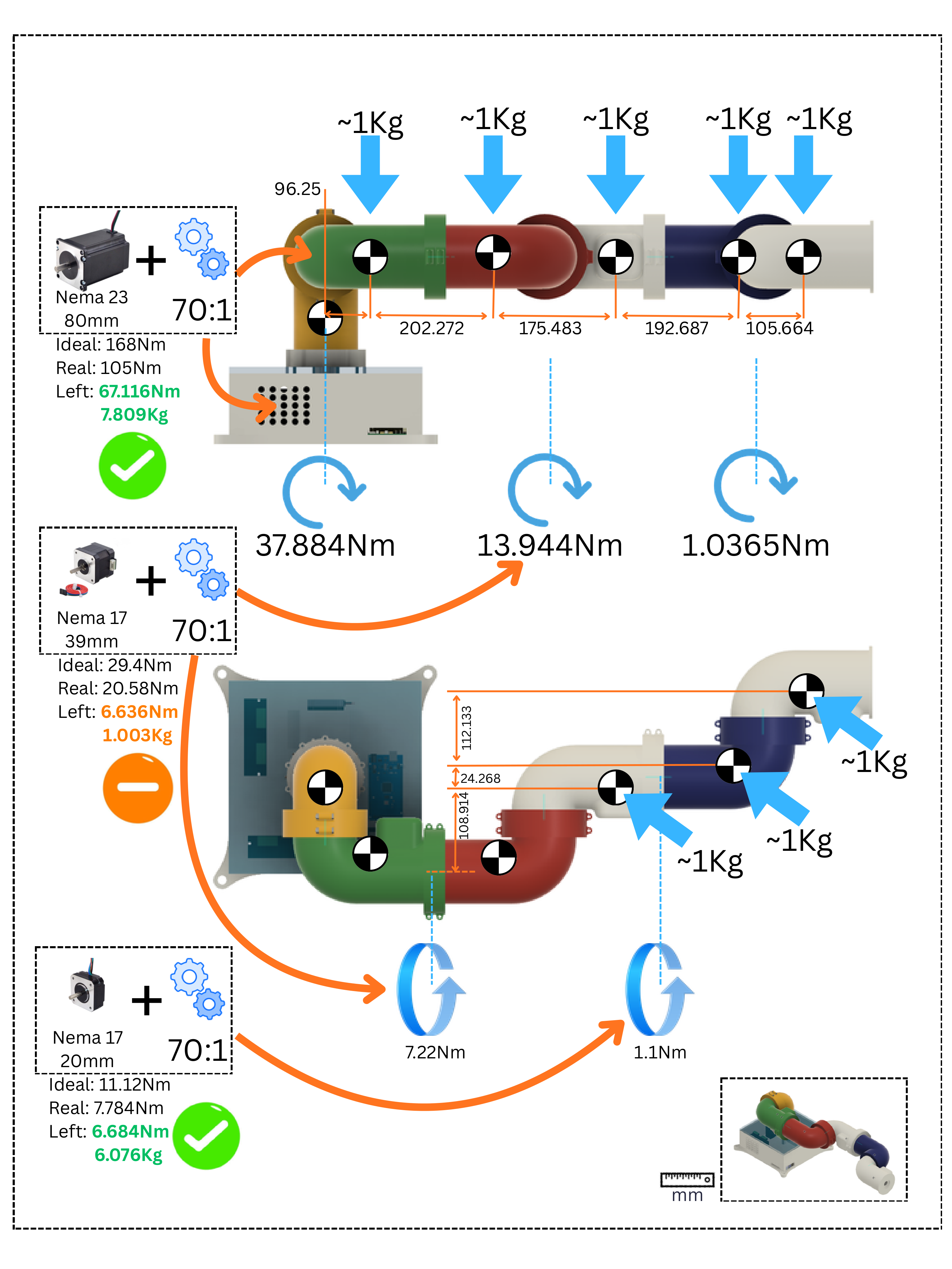
Side View (Fully Extended Arm)
This perspective calculates the torque required to hold the arm and its external payload in a static, fully horizontal extended pose. This pose is chosen because it creates the largest moment, maximizing the torque at the shoulder (joint_2).
Key details extracted from this view:
- External Loads: Five mass loads, each estimated at
~1Kg, are applied at various segments, representing components and a potential gripper payload. - Moment Arms (lengths in mm):
96.25,202.272,175.483,192.687,105.664. - Calculated Torques: The blue circular arrow icons and values (
37.884Nm,13.944Nm,1.0365Nm) are the calculated outputs required to hold this static position.
Top View (Base Rotation)
This perspective calculates the torque required for horizontal base rotation.
Key details extracted from this view:
- Mass and Centroids (mm): Four mass loads are labeled with an arrow and
~1Kg. Segment centroids are listed relative to the central pivot point:112.133mm,24.268mm,108.914mm. - Required Torques: The resulting blue circular arrows and values (
7.22Nm,1.1Nm) are the calculated torques needed for "Roll" or twisting joints (joints 3 and 5) along the axis of the arm.
The Motor Verification Process
The diagram contains orange mapping arrows that show which motor/gearbox combinations are being tested against which required torque points. For each combination, the diagram provides a critical engineering verification block (detailed in the summary table below) that translates torque into a margin of safety.
This calculation is presented as a margin of safety calculation: Real - Input Mapping Point = Left. The "Left" torque margin is then converted into a mass value in kilograms (Kg) to make the data more intuitively readable for real-world payload capacity.
| Diagram Validation Point | Input Source | Motor Analyzed | Gearbox Analyzed | Input Mapping Point | Ideal Torque | Real Torque | Left Margin | Mass Margin (Kg) | Validation Status |
|---|---|---|---|---|---|---|---|---|---|
| Valid Selection | Top Left | Nema 23 (80mm) | 70:1 | Side: 37.884Nm | 168Nm | 105Nm | 67.116Nm | 7.809Kg | Valid (Green Checkmark) |
| Failure Point (Critical) | Bottom Left | Nema 17 (39mm) | 70:1 | Side: 13.944Nm | 29.4Nm | 20.58Nm | 6.636Nm | 1.003Kg | At limits (Orange Minus) |
| Valid Selection | Bottom Left | Nema 17 (20mm) | 70:1 | Top: 1.1Nm | 11.12Nm | 7.784Nm | 6.684Nm | 6.076Kg | Valid (Green Checkmark) |
Analysis of Validations and Design Choices
The results derived from the table above represent the direct output of this engineering analysis:
- Valid Nema 23 Choice: The base horizontal rotation motor (Nema 23, 80mm with 70:1 gearbox) is verified to have a significant
7.8Kgmass margin. It maps its logic directly to the vertical pivot requirements (37.884Nm) from the side view and base rotation requirements (7.22Nm) from the top view. This combination is validated with a green checkmark, confirming the choice is valid. - Identified Nema 17 Failure: The analysis proves that using a Nema 17 (39mm) motor for the joint requirement of
13.944Nmis a point of failure. The margin is just1Kgand6.6Nm, marked with an orange minus sign. This data point drives a fundamental change to the mechanical design, ensuring this potential engineering bottleneck is resolved before component sourcing. This is why the model for link_2 will be modified so that it can handle different NIMA 17 types. Currently NIMA 17 with the body height of 39mm will be used. But the link structure will allow a larger NIMA 17, if more torque will be required. - Resolved Nema 17 Choice: Following the identification of the previous failure, the required torque mapping points were logically separated. A new analysis point shows that the final joint requiring
1.1Nmfor rotation can be successfully powered by a smaller, more compact Nema 17 (20mm) motor with a 70:1 gearbox. This combination provides a strong6.076Kgmargin and receives a green checkmark validation.
Conclusion
This load distribution analysis serves as the engineering baseline for the 7-DOF-arm-robot project. It moves motor selection from simple estimation to verifiable engineering data, directly driving crucial mechanical design decisions and component sourcing. It is an iterative verification tool used to guarantee mechanical soundness before any actual building occurs.
4. Assembly Process
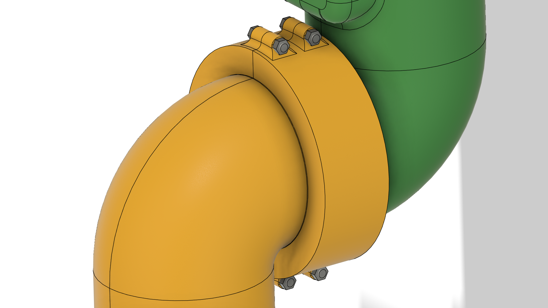
The mechanical assembly utilizes a "split-shell" design to accommodate the highly integrated internal components while ensuring structural integrity.
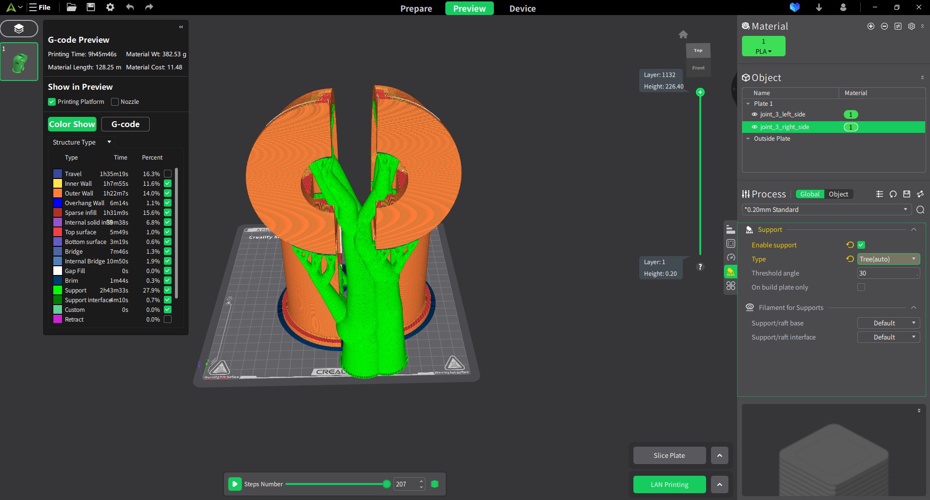
Split-Joint Design & Internal Access
Each joint housing is 3D printed in two separate halves. This split design is critical for the assembly process; it provides the necessary open clearance to manually seat the internal drivetrain. While the joint is open, the stepper motors, planetary gearbox, bevel gears, and the hollow shaft with its integrated slip ring are easily installed into their respective mounting channels.
Material Investment & Print Precision
The structural integrity of the 7-DoF arm requires a significant investment in material and print time. To support the calculated torque loads and house the internal bearing races, the joint walls are engineered with a 1 cm thickness.
- Material Weight: Each individual joint consumes approximately 400 grams of PLA filament.
- Structural Density: This high filament usage is necessary to ensure the 3D-printed races for the custom bearing balls do not deform under the stress of the 1-meter reach.
- Print Caution: Given that a full arm assembly requires several kilograms of filament, a "right-first-time" approach is mandatory.
The mechanical model was finalized only after exhaustive digital validation to ensure every gear-to-shaft connection and internal clearance was perfect. This rigorous design phase serves to prevent the need for costly and time-consuming reprints or mid-build mechanical revisions. By verifying all tolerances in CAD before starting the printer, the project avoids the common DIY pitfall of iterative hardware waste.